I have two blog posts for you focused on how you connect COB LED components into the electrical network. I mean, when you have either a single COB LED or an LED module based on SMD LED components assembled on a PCB board.
Compared to traditional lighting, connecting LEDs to the electrical network is a whole new world. LEDs need direct current (DC) to light them, alternating current (AC) will not work. There are also AC modules available but those are not covered here.
In this post I will concentrate on connecting single COB LEDs. In case you are interested in connecting LED modules, I will write about that in my next post.
LED driver
You will need an LED driver, which is actually an AC/DC converter. It converts the AC voltage/current of the electrical network into the suitable DC voltage/current needed by the LED component. You will find the requirements of the LED from a datasheet provided by the manufacturer. If you need help in choosing a driver, you can read our guide.

Figure 1. Example of an AC/DC converter, LED driver. This one is from ELT with dipswitches, which means that you can choose the driving current.
Connecting COB LED into the AC network
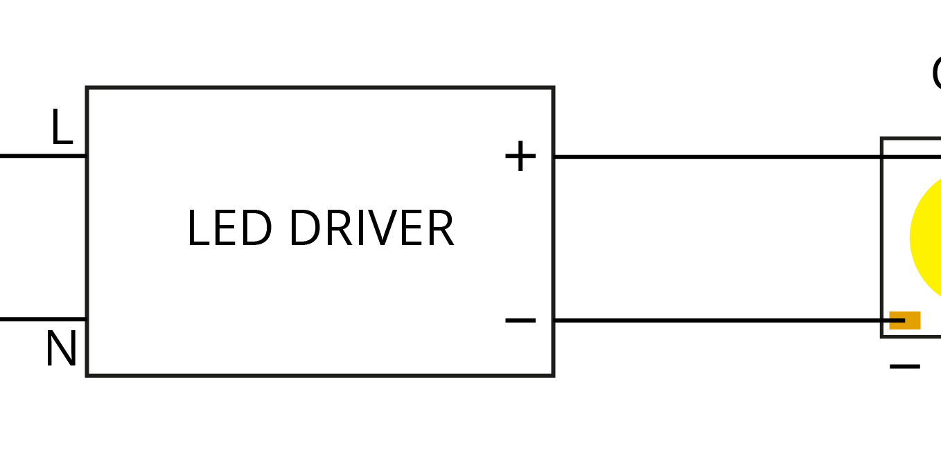
In case of COB, you will have to create a closed electrical circuit so that the electrical current can flow through the LED component. A COB LED is basically a diode in its electrical nature: the current can flow only in a forward mode. This means that you must connect the positive (+) solder pad of the COB LED into the positive terminal of the LED driver. In the same way, you connect the negative (-) solder pad of the COB LED into the negative terminal of the LED driver. See the Figure 2 below.
This way, you create the closed electrical circuit that is needed to feed current through the LED so that it gives light. This closed electrical circuit formed by the LED driver and the COB LED is called the secondary side of the LED driver. LED driver feeds the power and current into the closed electrical circuit, and thus through COB LED, on the secondary side.

Figure 2. COB-AC Network
On the primary side, the LED driver gets electrical power from electrical network, AC network. The terminals of the LED driver on the primary side are called line and neutral. They are connected into the line and neutral connections of the AC network. If you have an LED driver with cables, they are usually blue (neutral) and brown (line). Some drivers also have a ground terminal, which is usually connected to the luminaire body with grounding wire. However, the closed electrical circuit is needed also on the primary side; between the network and the driver.
Usually, you will need to use some kind of terminal block to connect the driver into the electrical network on the primary side.
Two options
Finally, as for physically connecting a COB LED into the LED driver, you have two ways to do it:
- solder the wires on the solder pads of the COB
- use solderless connectors.
In the first method, you manually solder the wire by using soldering iron with high temperature that melts the soldering material such as tin. After cooling, there is a joint between the wire and the COB solder pad. You need two wires, one for plus and one for minus solder pad.
In the second method, you use a solderless connector.
The solderless connector does the same effect as the soldered wire. You need the electrical connection also in this method, but you won’t need to solder the wire by melting tin. You just push the wire into the push-in terminals of the connector. Again, positive to positive and negative to negative terminal. They are marked on the connector. Basically these push-in terminals work with a combination of metal plates and springs that then make the connection to the solder pad of the COB LED.
The difference between these methods is, that unlike with soldered joints, in the solderless connector method the springs may loosen a bit over time and loss of contact may occur. Solderless connectors are generally thought to be more expensive than manual soldering.
In my next post I will go through the steps for connecting LED modules.


